
Plant
Shaped Aggregate Plant
Plants chasing cubical shape with VSI and careful tip maps.
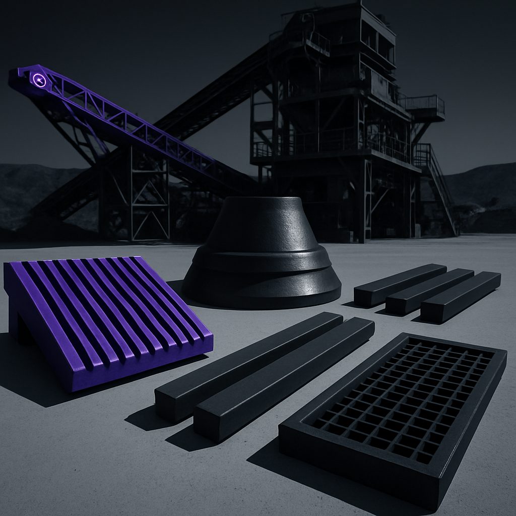
Parts for this plant
See our wear notes and printable resources for planning liner changes.
How the VSI shaped aggregate circuit is configured
Shaped aggregate plants after cubical product typically use a Vertical Shaft Impact (VSI) crusher as the final stage. The feed, usually well-graded minus 20 mm, arrives from a preceding cone or jaw. The VSI is set up to run in a choke-fed condition with a consistent, even feed across the table or rotor, to maximise collision energy and produce a cubical result. Oversize returns from the screen deck may be recirculated into the VSI, tightening the grading. A well-designed tip map ensures that wear is distributed evenly across all impeller tips, keeping power draw balanced and reducing out-of-balance conditions in the rotor.
These circuits are common where the end-users require concrete or asphalt sand meeting SANS grading, or for decorative stone where flakiness must be kept low. VSI settings, including rotor speed and feed ring position, are tweaked in line with cubical shape targets and plant tonnages.
Wear patterns and maintenance priorities in VSI aggregates
The main wear zones in a shaped aggregate VSI are the impeller tips, tip holders, anvil rings, and side liners. The impeller tip set takes the brunt of the impact. High-speed rock-on-rock action means tip erosion can be rapid if feed distribution is uneven, or if the tip map is not rotated according to the hours in service. Feed that is too fine or too coarse will also push wear towards either the centre or edge of the tips, leading to imbalance.
Wear can be accentuated by poor rotor balance or feed spillage, leading to vibration, shaft stress, and noisy operation. Keeping an eye on tip thickness and swapping tip positions helps stretch campaign life and avoids catastrophic tip failure, which can damage the rotor.
Critical parts for VSI shape circuits and their functions
We supply impeller tip sets for all major VSI models operating in cubical aggregate circuits. These tips, usually made from toughened martensitic steel with optional ceramic inserts, are designed to withstand repeated impact cycles and resist micro-chipping. The set includes left, centre, and right tips, which must be installed in the correct orientation and rotated as a set per the manufacturer's map.
Supporting parts include tip holders, backing plates, anvil rings, and side liners. Backing compound is used to lock liners in place, preventing movement under vibration. Rotor balance is maintained by careful matching of tip mass and regular inspection of lifting lugs for safe handling. Always use the correct liner bolts and torque as specified in the OEM manual, never guess or over-tighten.
- Impeller tip sets (with or without ceramic inserts)
- Tip holders and backing plates
- Anvil rings and side liners
- Backing compound and liner bolts
Planning tip changes, stock, and running through power cuts
VSI tip life depends on feed quality and the abrasiveness of the material: campaign times can range from 180 to 420 hours. Plan changes during scheduled plant downtime or predicted Eskom power cuts to avoid rushed strip-downs and reassembly in the dark. Keep at least one full tip set and associated hardware in stock on site, along with fresh backing compound ready to mix.
Regularly map and record tip positions, hours in service, and wear profiles. If your plant is in an area known for frequent power supply interruptions, especially on the Highveld or in the Cape southeaster, coordinate with your maintenance team to slot in tip changes when production is paused. For urgent parts supply or technical advice, drop us a mail through our contact form so we can organise quick delivery from our Sunnyrock yard or nearest showroom.
What our Crusher Wear Parts customers say
Verified Google reviews